
| Generating motion on rough terrains |
 An autonomous rover will eventually be facing
complex terrains. It should thus be given the tools that will help
it decide if its mechanical structure is able to traverse those
areas, or if it should rather avoid them and plan new trajectories
accordingly.
An autonomous rover will eventually be facing
complex terrains. It should thus be given the tools that will help
it decide if its mechanical structure is able to traverse those
areas, or if it should rather avoid them and plan new trajectories
accordingly.
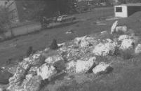
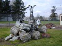
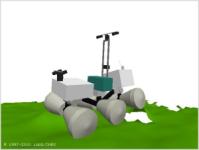
Lama's chassis was conceived to traverse quite rough
terrains, such as the one shown on the image on the right. For such
terrains it is necessary to consider the geometry of the
ground in order to compute feasible trajectories and
guarantee that the rover will be able to travel through the
complex areas. To achieve a true autonomous navigation, the
dynamic aspects should also be taken into account (see the
locomotion section).
As of today, a pure geometrical method is embedded on board
Lama. It is based on a geometric placement function and a
rudimentary reactive motion generation function, which are quickly
described below. You should refer to
[Bonnafous 2001] for a more complete
description.
1. A geometric placement function
The geometric placement function can compute the complete chassis configuration, given the current position of the rover and the current digital elevation map. This function is off course highly robot-dependant, but the algorithm we use is quite generic and could be adapted with few modifications to other chassis (e.g. for Dala). As of now, it's been used only on Lama.
For Lama, six angles are computed: the global pitch and roll of the chassis, as well as the pitch and roll of the front and back axles (relatively to the middle axle). The algorithm is split into two main steps:
- Placement of the middle (main) axle
- Placement of the front and back axle
Both steps use the same individual axle placement function, and the second step use one additional constrained placement function (which is constrained by the position of the middle axle).
1.1. Single axle placement function
On lama, axles are made of two rigidly connected wheels. The placement consists in computing the roll and the height of the whole axle, given an horizontal position (x,y,theta) on a DEM. The algorithm is quite simple, and its main step is depicted on the two figures below.
Compute the elevation of a reference point located on each wheel, depending on the wheels profile and on their current roll (which is initially 0 --- horizontal, as show on the left image above).
Compute a roll increment (noted phi on the images above) based on the height gap between the two wheels.
If the roll increment is bigger than a given threshold, update the current axle roll and iterate over step 1 (right image above).
The roll increment is smaller than the threshold; the axle is placed.

1.2. Constrained axle placement function
This function is used to compute the placement of the front and back axles, which are free to rotate in pitch and roll around the middle axle. The placement of the front and back axle will give the global pitch and roll of the rover.
The principle is the following:
The front axle is initially placed in front of the middle axle, as if the robot were on a flat ground. This gives an initial horizontal position for the axle (x,y and theta).
The individual axle placement function is called, and is used to compute the roll and the height of the front axle.
The horizontal position is updated, so that the axle remains at the same distance of the middle axle, and the algorithm iterate until the horizontal position doesn't change more than a given threshold.
The two images below give an idea of the placement results we are able to obtain. The placement function for the six wheels takes about 10ms to complete on a 5x5cm DEM and a 350MHz G3 processor.
2. Reactive motion generation
Given the geometric placement function, we developped a reactive motion generator, suited for navigation on complex terrains. The principle resembles much the arcs generation, though some improvements regarding predictability have been made.
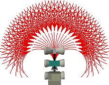
The above figure shows a set of arcs, recursively nested, on which a set of regularily spaced rover configurations are evaluated. Both the number of arcs and the nesting depth are configurable. On Lama, we use 21 arcs on the first level, and 11 arcs on the second level. The arcs are 2m long, and contain 20 configurations (spaced by 10cm). The nesting allows a more predictive solution to be found.
An A* algorithm is used to explore the tree formed by the successive configurations and a cost function helps determining the best (lowest cost) arc to be followed at the current position. The cost contains two parts: a dangerousness and an interest value.
The dangerousness is computed thanks to the chassis configuration
angles: each angle 'a' has an upper limit 'm' and the dangerousness
relative to 'a' is 'd = m/(m-a)^2'. The maximum 'd' obtained for
all the chassis angles is the global dangerousness of the
configuration.
The interest value is the Dubbins distance to reach the goal from
the current position.
Finally, the cost of one node of the tree is the dangerousness
multiplied by the distance between two configurations, plus the
interest value.
Once a good arc has been found, it is followed during a variable distance (configurable), and the process iterates. On a 350MHz G3 processor, one iteration lasts between 300ms and 1500ms (depending on the terrain and the A* performance).
| Related Publications |
| [Bonnafous 2001] | [related pages] [abstract] [download] [copyright] [BibTeX] [top] | |
| ||
| People Involved |
Simon Lacroix, Anthony Mallet, David Bonnafous.
|
Robots
|
Rovers Navigation

Autonomous Blimps
|
Multi-Robot Cooperation
|