
| Enhanced motion control for Lama |
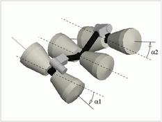
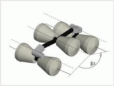
Lama is Marsokhod rover: its chassis is composed of three pairs of
independently driven non-directional wheels, mounted on axles
that can roll relatively to one another, thus giving the robot high
obstacle traversability capacities (note that the length of the chassis
can be actively controlled - see peristaltic motion mode).
Basic control of a Marsokhod rover chassis
The robot motions are defined by a couple of translational and
rotational speeds, which is converted into 6 reference angular speeds
for the 6 wheels of the robot. The wheels being non orientable, the
robots turns in a skid-steering way: a differential of speeds must be
applied to the right and left wheels of the center axle. This causes the
rotation of the center axle. Of course, a similar and compatible
operation must be done on the 2 other axles so that the whole robot make
the desired turn.
The basic motion control consists in applying the same reference
speed on the 3 wheels that are on the same side of the
robot (wr on the 3 right wheels and
wl on the 3 left wheels).
The Terrain Adaptative Locomotion Control (TALC)
The problem
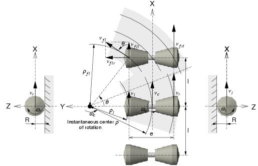
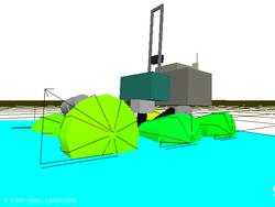
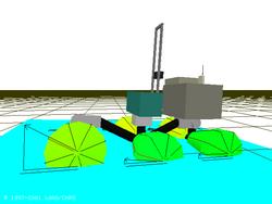
This basic method does not take into account the great influence of the shape of the terrain. Indeed, the 3 wheels on a same side should have the same linear speed's projection on a common geometric plane: actually, the direct application of wr on the 3 right wheels and of wl on the 3 left wheels forces some wheels to slip on uneven terrains.
 |
 |
|---|
This phenomenon is illustrated in 2D and 3D on the figures above: for each wheel, the angle between its linear speed and the ground has to be taken into account in order to prevent slippages.
The solution
In order to prevent slippages due to terrain irregularities, the purpose
of the "Terrain Adaptative Locomotion Control" (TALC [Peynot 2003]) is to have the effective linear speeds
of the 6 wheels respect the following condition:
The linear speeds of the 3 wheels on a same side must have the same
projection on a common geometric plane.
For instance, if one wheel has to climb over a rock whereas all the
others stay on a flat terrain (as in the 3D figures above), a higher
speed will be applied to the climbing wheel to compensate for the
influence of the new angle between the wheel's linear speed and the
ground. If that condition is respected at any time, the TALC
should not induce any slipping situation. Of course, this does
not mean that no slippage will ever actually occur! But the application
of TALC reduces significantly the slippages.
Implementation
Thanks to the various proprioceptive sensors available on-board Lama, the configuration and attitude of the robot can be known at any time. Using this data and their derivatives over time, and given the reference linear speed v to achieve, the direction gamma of the linear speed of each wheel with respect to the main evolution plane is estimated. The correction to apply to the reference speed is a simply a cos(gamma).
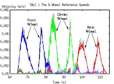
Here is a small movie (1.7 Mo) showing the directions of the linear wheel speeds estimated when the rover climbs over a rock. The curves below illustrates the elementary wheel speed corrections generated by the CLA for a 5 cm/s straight motion during which the left wheels climb over a small rock: each wheel elementary speed is augmented as it goes up and down the rock.
| Locomotion Fault Detection |
In some situations on very rough terrains, because of excessive slippages, the rover might have great difficulty in moving or might even stop moving forward, even if in the meantime its 6 wheels keep on turning. Such situations are Locomotion Faults. On board autonomous rovers, it is crucial to be able to detect such faults, to correct them or to trigger an other moving strategy. This is performed through the computation of a Locomotion Efficiency Index, which gives an estimation of the actual efficiency of the rover locomotion at any time, on the basis of three speeds coherence indicators.
Linear Speed Coherence
As elements of the same solid, the expressions in a common referential
of the speeds of 2 robot's wheels (A & B) on the same side should
satisfy certain relations between them. These expressions are
permanently computed on the basis of the measured wheels speeds and the
angles estimations produced by the TALC. The speeds are coherent
if expr(A)=expr(B): the difference expr(A)-expr(B)
therefore gives an estimation of the incoherence between the
speeds measurements. Two average indicators of incoherence are
calculated at each time sample, one for each side of the robot.
Rotation Speeds Coherence
On board Lama, a quite precise measure of the robot rotation speed is
given by a fiber-optic gyrometer (wGyro). This speed
can also be estimated using the wheels speeds measurements by:
wOdo = (Vr-Vl)/e where
Vr and Vl are the linear speeds
of a right wheel and a left wheel respectively (on the same axle), and
e is the axle length. The expression of Vr
is R*wr*cos(gamma) where gamma is an angle
estimated thanks to the TALC module, R is the wheel radius and
wr is the measured angular speed of the wheel. The
average of all the (wOdo - wGyro)
computed is the third indicator, which gives an estimation of the
incoherence of the rotations speeds.
Locomotion Efficiency Index
To detect locomotion faults, the three computed indicators are normalized to fit in a [0;1] range, 0 representing a perfect situation (no slippage at all), and 1 the supposed worst situation. This normalization is a function of the linear and angular reference speeds Vref and wref: indeed, the rover needs to slip in some situations (especially when it has to turn, due to its non-directional wheels), and the faster it goes, the more it needs to slip.
Finally, the Locomotion Efficiency Index is currently an average of the three indicators obtained. Locomotion Faults are detected when this average exceeds a threshold during a time period greater than an other threshold. Relevant values for these two thresholds were determined on the basis of experimental observations.
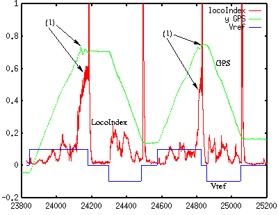
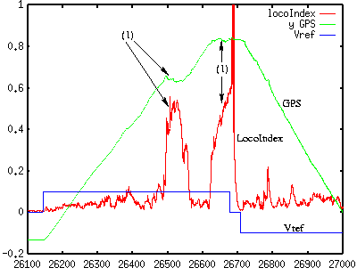
The two following figures illustrate the behavior of the locomotion efficiency index, shown in red. The purple curve show the evolution of the robot position (measured thanks a RTK differential GPS), and the blue curve is the reference speed. The detected locomotion faults are indicated by the (1) marks on the figures.
| Related Publications |
| [Peynot 2003] | [related pages] [abstract] [download] [copyright] [BibTeX] [top] | |
| ||
| People Involved |
Sara Fleury, Anthony Mallet, Thierry Peynot.
|
Robots
|
Rovers Navigation
|
Autonomous Blimps
|
Multi-Robot Cooperation
|